
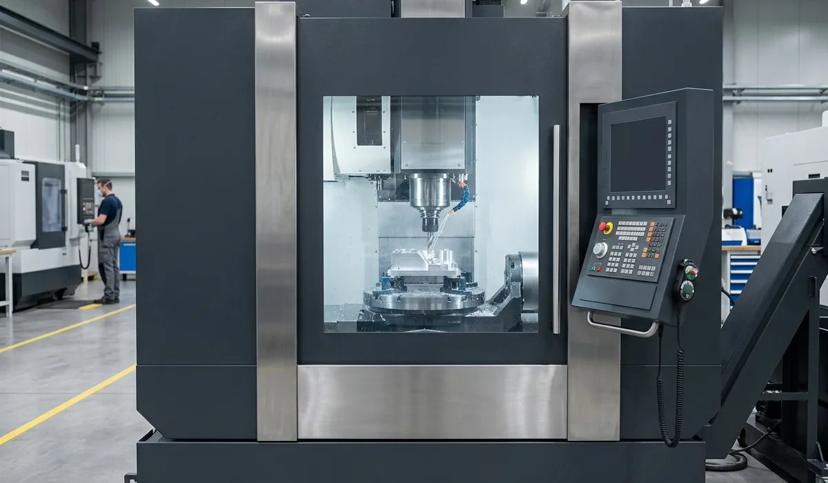
The Core Dilemma: Work Envelope vs Dynamic Agility
When evaluating 3-axis vertical machining centers, manufacturing plant managers and lead CNC programmers routinely debate between the VMC850 and VMC650. While both machines share our heavy Meehanite HT300 resin-sand casting foundation, their mechanical kinematics cater to distinctly different production profiles.
Understanding these structural differences will directly influence part cycle times, surface finish quality, and equipment capital expenditure amortization.
Key Structural & Kinematic Disparities
| Engineering Parameter | VMC650 Precision Center | VMC850 Heavy Machining Center |
|---|---|---|
| X / Y / Z Axis Travel | 650 × 400 × 500 mm | 850 × 500 × 500 mm |
| Worktable Dimensions | 800 × 400 mm | 1000 × 500 mm |
| Maximum Worktable Load | 450 kg | 600 kg |
| Machine Net Weight | 4,200 kg | 5,500 kg |
| Spindle Drive Architecture | Direct-Coupled (Up to 12,000 RPM) | Dual-Winding / Direct (8,000-10,000 RPM) |
| Primary Target Production | 3C Electronic Housings, Medical, Electrodes | Automotive Powertrain, Die & Mold, Cast Steel |
1. Spindle Power Curves and Material Removal Rates (MRR)
The VMC650 is tuned for high-acceleration machining. With rapid axis traverse rates of 36 m/min and an available direct-drive 12,000 RPM spindle, it reduces non-cutting tool transit time significantly. When machining aluminum aerospace manifolds, copper graphite electrodes, or 3C electronics cases with small-diameter end mills (Ø3 - Ø12 mm), the VMC650's lower moving mass delivers noticeably crisper surface finishes without tool dwell marks.
Conversely, the VMC850 incorporates an extra 1,300 kg of cast iron in its column and base. This substantial mass dampens low-frequency cutting harmonics during aggressive face milling on alloy steels (such as 4140, 4340, or cast ductile iron). The BT40 spindle on the VMC850 delivers sustained torque across the 1,500 - 4,500 RPM range, allowing cutter diameters of Ø63 to Ø100 mm to achieve heavy depths of cut without chatter.
2. Geometric Freedom & Multi-Fixture Setups
The additional 200 mm of X-axis travel (850 mm vs 650 mm) and 100 mm of Y-axis cross-travel on the VMC850 provides manufacturing flexibility that extends beyond individual part size:
3. Factory Floor Footprint and Operational Economics
For facilities where shop floor area is constrained, the VMC650 requires only 2.1 × 1.9 meters of floor space compared to 2.8 × 2.3 meters for the VMC850. Power consumption is also approximately 15% lower during high-speed finishing cycles.
Engineering Recommendation
Consult an SDS Senior Application Engineer at xiuc32860@gmail.com with your 3D CAD step files for cycle time simulation.